| Part | Radio Shack Part Number | Price | Picture |
| LED | 276-270A | 1.99 | |
| Switch (SPDT) | 275-693 | 1.99 | 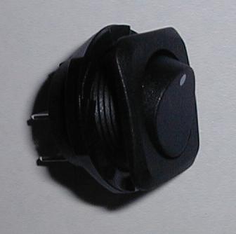 |
| Jack (5.5/2.1 coax) (2 in a pack) | 274-1563 | 1.69 | 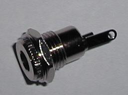 |
| Plug (5.5/2.1 coax) | 274-1569 | 1.99 | 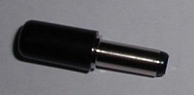 |
| Fuse Holder (2 in a pack) | 270-0739 | 1.19 | 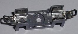 |
| Extension cord | 270-1592 | 6.99 | 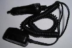 |
This time I wanted a 12V source at the rear of the ZJ and ideally it would be a standard "ciggy lighter" type outlet. Problem, there isn't enough room behind that plastic to install the outlet so a work around was in order.
A quick list of the parts:
| Part | Radio Shack Part Number | Price | Picture |
| LED | 276-270A | 1.99 | |
| Switch (SPDT) | 275-693 | 1.99 | |
| Jack (5.5/2.1 coax) (2 in a pack) | 274-1563 | 1.69 | |
| Plug (5.5/2.1 coax) | 274-1569 | 1.99 | |
| Fuse Holder (2 in a pack) | 270-0739 | 1.19 | |
| Extension cord | 270-1592 | 6.99 | |
| The first thing to do was to remove the lighter plug from the end of the extension cord. After a bit of solder and some heat shrink I came up with this. I have to admit it would be much more elegant to have a standard outlet available but they are just too deep for the body plastic and it would take some woodworking or metal cutting to get one in there. Something I just didn't feel like doing. Maybe later if this proves to be too annoying. :) | 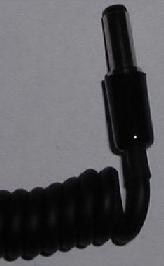 |
| This is the connection at the bottom of the "D Pillar" The wire is a 18 Gauge Red with Black Stripe. There is a larger wire in that bundle that is pink with a black stripe. That wire feeds the rear door lock motor. Don't tap it, ok? When in doubt pull fuse #1 (20A) from the drivers door fuse block. | 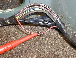 |
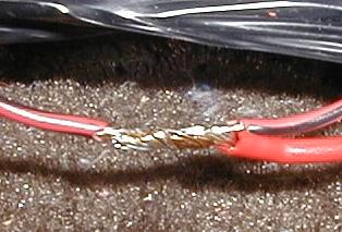
| Nice and splicey. I used a slightly larger gauge wire to run
the power up. This isn't the way it should be done but there was
no way in (DELETED) I was going to go buy a 4 ft stretch of wire just for
this project, mkay? ^_^
Oh. This is just the first step. To finalize I soldered the connection and wrapped it with self vulcanizing rubber tape. Don't ever leave twisted wire as the only connection, it's bad, very bad. |
 |
| Well, now for the location. I chose the passenger side of the ZJ since it wasn't obscured by the spare tire and a location on the side that had a corresponding depression in the body metal that gave me just enough room. Do be sure to insulate behind the connector. Especially the socket. In this pic you can see the fuse holder positioned so it's easier to get at and the LED mounted in the plastic panel. | 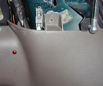 |
| In this pic you see the switch mounted below the LED. The spacing was arbitrary but it looked ok. There is a 1/4" gap between the switch and the LED. | 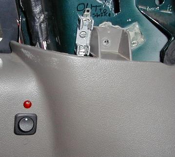 |
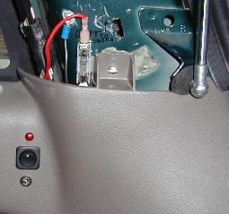
| Now I added the outlet at about the same spacing. The power line
has been connected and the ground line
has been fitted to the body. The maximum this circuit can pull (in combination with the power antenna and trailer tow group) is 20 Amps (fuse1). The fuse I chose to use is a 5A fuse based on the highest power I anticipate drawing from this plug. Although the components are rated at a minimum of 30A. |
 |
| Well, this is the finished product with the switch on. As you can see the light is just bright enough to be seen at night if it's left on by mistake. And with the current draw of the LED being 15ma, well, it could run for a very loooooooooooooooong time. | 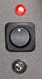 |
| This is a pic with the power cord attached. The only fault I can pick is that if you stick a key or some other metal bit in that socket you can pop the fuse. :/ I wish there was a DC jack with a switch way at the back. But this sitll is better than having to run a stupid cord from the forward ligher. And I don't need to leave a key in the ignition to have power. | 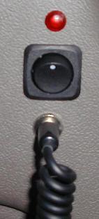 |